Fender Dual Showman Diagnosis and Repairs
Second Pass -- 2020 -- and Success!
Note: this web page is currently being created - as I tackle this project -- again.
Fender Dual Showman silver face Model AB763 (1968)
After failing to fix this amp in 2015, I set it asside to concentrate on other projects. This past year -- with the covid quarantine -- I checked off many of those with some time left over. So now I have tackled this amp with renewed vigor.
- History of this Amp and Project Background (2015):
- Research on Tube Amp Design and Truobleshooting (2015):
- First pass at fixing this amp (2015).:
Summary of what I did during my 'first pass' at fixing this amp:
- Replaced all 4 power amp tubes (6L6GC) with matched set from Antique Electronic Supply
- Replaced all electrolitic capacitors with Cap Set from Antique Electronic Supply
- Measured the following Plate Dissipation with new 6L6 power tubes installed:
Tube
PairXformer
ResistanceXformer
Voltage DropPlate
CurrentPlate
VoltagePlate
DissipationOuter 34.7 Ohm 1.14 Volt 0.0304 Amp 343.0 Volt 10.4 Watt Inner 36.8 Ohm 2.20 Volt 0.0167 Amp 343.0 Volt 5.48 Watt
Diagnosis and testing for 2d pass:
- Left channel works but volume is still not good (maybe 1/3).
- The right channel (with Vibrato) doesn't work at all.
- All tubes light and there's no hum or noise (with new 6L6 tubes).
- No physical sign of any other preious work.
- Measured the following Plate Dissipationwith new 6L6 power tubes installed AFTER replacing all grid and screen control resistors:
Notes:Tube
PairXformer
ResistanceXformer
Voltage DropPlate
CurrentPlate
VoltagePlate
DissipationOuter 34 Ohm 1.31 Volt 0.0386 Amp 349.6 Volt 13.5 Watt Inner 36 Ohm 1.52 Volt 0.042 Amp 348.4 Volt 14.7 Watt - Maximum rated Plate Dissipation for 6L6GC power tube is 30 Watts.
- Recommended operating power is 75% (21.0 Watts). These values are less than 50%, but...(see #3)
- I'm not worried about these power values being a little low because I will only use this amp around the house and don't need a lot of power. The sound quality is just fine and the tubes run cooler and, therefore, will last longer.
Diagnostic and Repair.
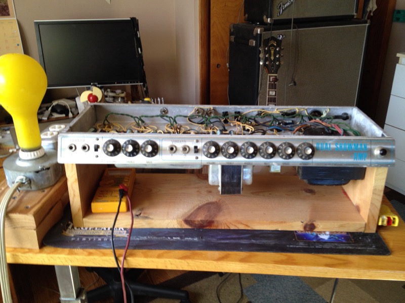
Amp on work stand
Work Stand
First step is to remove the amp from the cabinet. I made this simple stand to support the chassis with the component side up.
To the left of the stand you can see the 250 Watt light bulb that is the basis of the safety interlocked power source. If the amp were to draw a ton of current (due to a short, etc.) this light bulb will shine brightly.
Click on picture to enlarge
Uncle Doug YouTube video discribing this Current Limiter: )(link)
Filter Capacitor Re-Cap
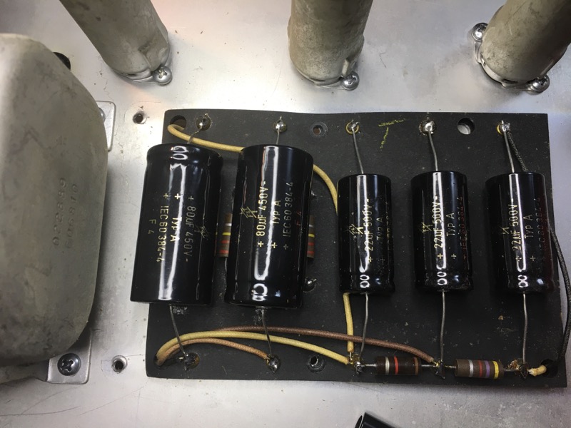
Replace Electrolytic Filter Capacitors
During the first pass at fixing this, I did a Re-Cap of all the electrolytic capacitors. These all tested out-of-spec. One grid bias cap and one signal filter cap that had cracked shells.
You can see the filter capacitor resistors next to these caps. I have replaced all of these carbon resistors (of marginal values) with new ceramic resistors which reportedly hold up better to these high voltages.
Click on picture to enlarge

Location of caps in circuit

Replacing Resistors
Replace Plate and Screen Resistors on Power Tubes
The Screen and Grid blocker resistors on these four 6L6GC power tubes were reading over specs so I replaced the old carbon composite resistors with new "fire-proof" ceramic resistors. These resistors are mounted on the base of the power tubes so they get pretty hot in normal use.
Click on picture to enlarge
The blue resistors in the picture are circled in green. The grey resistors are circled in red.
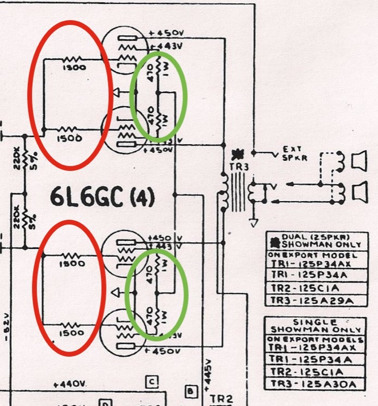
Location of resistors in circuit
So all these new parts were needed but none of this fixed the problem with the Amp. The "Normal" channel was grosely under-powered. And the "Vibrato" channel didn't work.
The Solution -- finally

Negative Feedback Resistor
Fix for Problem #1:
While I was checking resistor values, I touched the meter probe to this resistor and one end moved. There was no way I could have seen this -- no matter how hard I looked. This resistor controls the negative feedback current to the output transformer.
The end of this resistor is supposed to be attached to that eyelet. I imagine it vibrated loose. The wire should have been bent down and inserted in this eyelet before soldering.
This fixed the "Normal Channel"
Actually, it fixed both channels since this is circuit is part of the power stage that amplifies both channels.
Click on picture to enlarge
Location of resistor in circuit
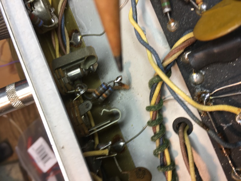
Plate Blocker Resistors
Fix for Problem #2
Since the Normal channel worked, I could illiminate everything after the pre-amp stage as well as all the power supply. I poured over the schematics, checked voltages on all the pre-amp tubes, double and triple checked all the signal paths through this circuit
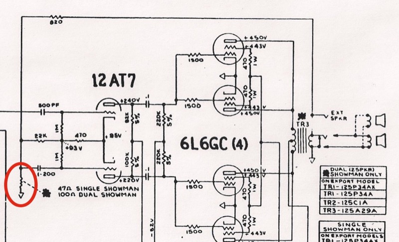
Then I took a close look at the input jacks and the twisted wire connection where the two screen blocker resisters (one for jack #1 and one for jack #2) join the wire that runs to the screen on the pre-amp tube. I thought to myself; "This doesn't look like enough solder." So I re-soldered it.
This fixed the "Vibrato Channel"
Click on picture to enlarge
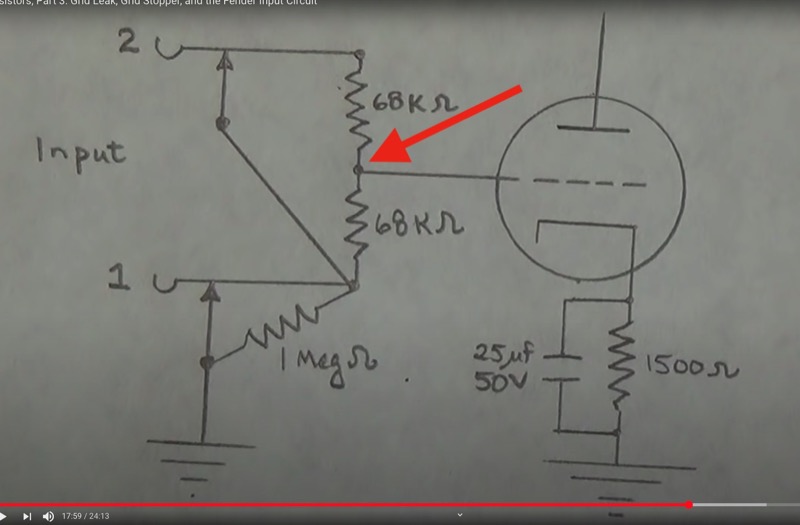
Location of connection in circuit
Note: This drawing is from one of Uncle Doug's videos on YouTube (link).
References:
Background and Component Function
Here are a few of the youtube videos by Uncle Doug. He does an excelent job of explaining the function and operation of the components that make up these Amps.
- How Tube Amplifiers Work (Series of YouTube videos from Uncle Doug0 (link)
- Resistors, Part 1: Their Circuit Function & Practical Applications of Ohm's LawResistors (link)
- Capacitors in Audio Circuits (Series of YouTube videos from Uncle Doug) (link)
Conclusion:
As I studied these circuits and the theory behind them, I found a number of things that weren’t quite right and I fixed these by replacing leaking capacitors and worn out resistors and noisy power tubes. But none of this fixed the main problem; one channel weak and the other barely working at all. This was very frustrating — for over 5 years!
Until, one day when I was testing the values of resistors I touched the probe to the ends of one particular resistor and it moved (the resistor in the negative feedback loop). One of the ends had disconnected from the solder joint and there was no way I could have known that just by looking at it. Fixing this brought back the good channel to full power but didn’t help the bad channel at all.
So I studied more youtube videos and scratched my head over more schematics. Many places in this amp the makers had twisted wires together and soldered them (by design). One such place was on the input jacks for the bad channel (the grid stopper resistors from each input jack join the feed wire to the pre-amp grid). I’d looked at this particular joint many times and even tested continuity across it. The last time I looked at it I thought; “Gee, the solder looks a little sparse on this joint”. So I added a little more solder and voila — just like that — problem solved. Everything worked! It seems like this happens a lot; the problem is fixed by something quite ‘simple’.
Epilog:
Throughout my readings on these classic Fender amplifiers, folks expound on the quality of sound from the classic componentents. They fixate on how the original resistors, capacitors, and tubes imbew these amps with a "Fender" sound that can be somehow lost when substituting 'modern' parts. I happen to agree wholeheartedly, and this is why I've resisted letting anyone else work on this amp. I want to know exactly what is replaced and why. I have tried to use only the models -- from reliable sources -- that have been certified to be as close to OEM as possible.
Once I had everything working properly in this amp I re-installed the original RCA brand 6l6GC power tubes to see if these were actually still good. I checked the plate dissipation on these and they were in the same neighborhood as the new tubes except that one pair were quite a bit higher than the other pair.
- Note: In the Dual Showman, these output tubes are paired together and wired in paralell so plate dissipation measurements (using the output transformer method) will average the two inner and the two outer pairs. So to directly measure individual tube values, I have built the bias probe described in this Uncle Douge Video . The measured plate dissipation on one of the paired tubes was higher than the average but not so much to worry about.
Well, the amp sounded terrible with these old tubes. It had a nasty hum and it was very noisy when played. Two of the 6L6's (the inside pair) were much brighter and were way too hot to touch. So I quickly swapped in my new tubes again.